1. Introduction
Cacao implements modal control, where the input signal (WFS image for example) is linearly decomposed as a sum of modes. The coefficients of this decomposition represent the input measurement in the control modal space. The coefficients are then processed to compute a modal control command.
At the heart of the modal control are the control modes, a set of modes with corresponding representations in input (WFS) and output (DM) spaces. What should these modes be ?
A few options are discussed here, ordered with increasing complexity and performance.
1.1. CACAO control modes format and conventions
Control modes are stored are stored as corresponding pairs of WFS-space and DM-space modes, with file names conf/CMmodesWFS/CMmodesWFS.fits and conf/CMmodesDM/CMmodesDM.fits respectively.
2. SVD modes (straight SVD of response matrix = pseudo-inverse)
SVD modes are often used for AO control. They are the modes computed by singular value decomposition of the system response matrix. They allow for a regularized pseudo-inverse of the response matrix to be used for control. The SVD modes are ordered by singular value, with the first modes corresponding to the unity norm DM actuation producing the strongest WFS response.
2.1. Why SVD modes ?
Using SVD modes for control allows for identification of the WFS null space, corresponding to DM actuations that cannot be measured by the WFS. In the presense of noise, the null space is a fuzzy concept, as some DM commands will produce a weak (but non-zero) WFS signal. The control law needs to filter modes with weak or zero response, but should to do so in a controlled way, balancing the need to control as many modes as possible, but avoiding amplifying noise.
The SVD modes allow for this tuning, where the strongest modes (the ones best sensed by the WFS) are controlled with high gain, and the modes that are weakly sensed are controlled with low gain. In modal control with SVD modes, control gains are tuned for each mode, primarily as a function of how well a mode is sensed.
2.2. SVD modes - Example
The SVD modes are computed from the response matrix, which consists of pairs of DM poke modes and their corresponding WFS response. The two figures below show the RM poke modes and the corresponding WFS response. Only the first 48 modes are shown.
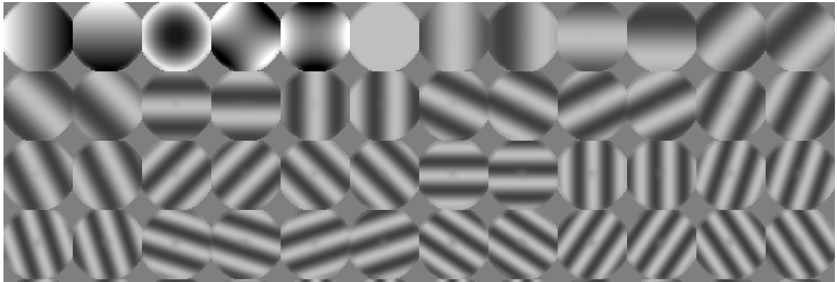
The response matrix DM mode were here created by concatenating the first 5 Zernike modes, and Fourier modes of increasing spatial frequency.
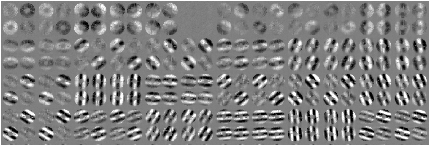
Here, we used a pyramid WFS, so we see that each of the 48 modal responses (arranged here in a 12x4 grid) consists of 4 pupil images.
To compute the response matrix DM and WFS modes above:
# Compute RM modes in Zernike+Fourier basis
#
# -t 1.0 : do not amplify TT
# -a 0.0 : do not apply power-law to Fourier modes
#
cacao-aorun-033-RM-mksynthetic -t 1.0 -a 0.0
Now we compute the control modes by SVD with the cacao-aorun-039-compstrCM command:
# Compute SVD modes
#
cacao-aorun-039-compstrCM
The DM control modes (file conf/CMmodesDM/CMmodesDM.fits) are shown below.

The first mode (top left) is the DM pattern that will generate the strongest WFS response.
2.3. Limitations of straight SVD modes
A key limitation of SVD modes, apparent in the figure, is that they do not take into account the statistical properties of input disturbances. The dominant SVD modes (largest singular value) may be quite different from the modes with the strongest amplitude in atmospheric turbulence.
Also, we may want to force control modes to match some specific target. For example, the first two control modes may need to be as close as possible to Tip and Tilt so that pointing can easily be offloaded to another loop. We may want the control modes to be ordered by spatial frequency, as the statistical properties of atmospheric turbulence (amplitude, speed) are driven by spatial frequency.
3. Tuning the response matrix prior to SVD computation
We show here how we can still compute the control modes by SVD, but with a different input response matrix. This approach mitigates some of the issues of the straight SVD computation above.
With knowledge that some modes have stronger amplitude in the input, we can build an amplitude-aware response matrix (RM), where the RM is now a better representation of input disturbances.
3.1. Amplitude weighting of Zernike + Fourier response matrix
The first approach is to construct a sensible set of DM modes from Zerkine and Fourier modes, and set their amplitudes to capture the expected statistical properties of input disturbances. Here, we set the first 5 modes to be Zerkines (Tip, Tilt, Focus, Astigmatism), and subsequent modes to be Fourier modes of increasing spatial frequency. We multiply the tip-tilt amplitude by 8x as we expect some pointing vibrations, and we gradually decrease the amplitude of high spatial frequencies with a power-law.
This feature requires a zonal response matrix and a geometric representation of the DM, where DM actuator pixel coordinates correspond to actual geometrical position.
A synthetic set of modes, ordered by spatial frequency, is created in DM space.
# Compute RM modes in Zernike+Fourier basis
#
# -t 8.0 : amplify TT by 8x
# -a 1.0 : apply power-law to Fourier modes
# use -c option for max spatial frequency [CPA]
# use -z option for number of Zernike modes
#
cacao-aorun-033-RM-mksynthetic -t 8.0 -a 1.0
The corresponding RM DM modes now exhibit the desired modal amplitudes:
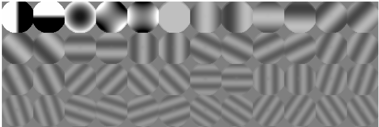
The WFS response to these modes is computed from the zonal response matrix. The synthetic RM modes are weighted by spatial frequency prior to computing the CM. Doing so will ensure that the resulting CM is approximately ordered by spatial frequency.
The SVD modes computed by cacao-aorun-039-compstrCM will now prioritize modes based on both WFS sensitivity and input amplitude.
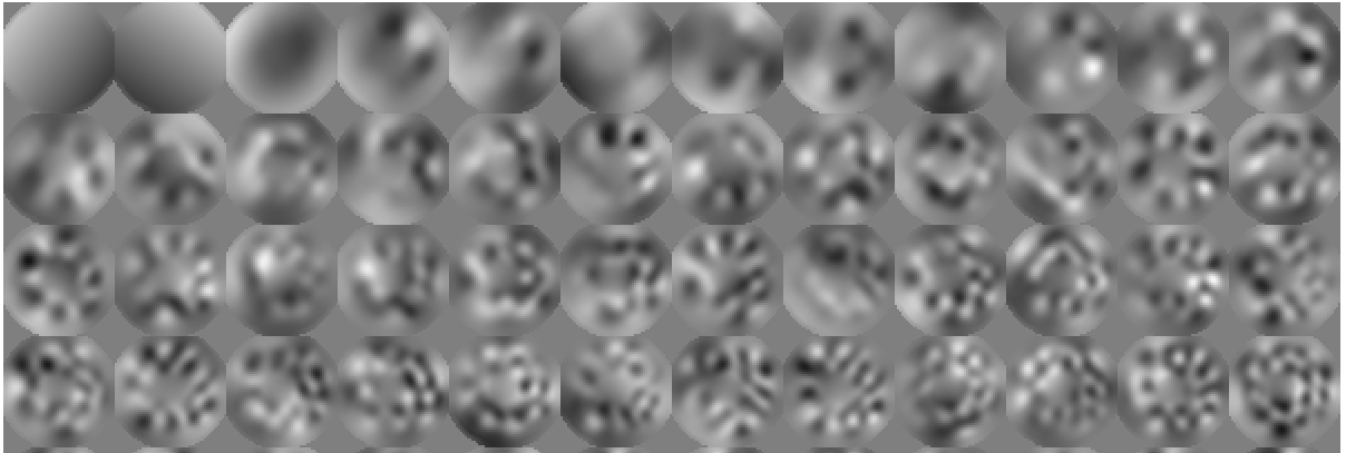
The new control modes are now approximately ordered by spatial frequency, with the first two modes tip and tilt, and the third mode close to focus. These control modes are much improved compared to the ones obtained by straight SVD of the response matrix.
3.2. Atmospheric turbulence KL modes
The response matrix modal weighting presented in the previous section is a very approximate way to capture the physics of atmospheric turbulence. A more rigorous approach is to simulate, for the AO system considered, the WFS response to a large sample of atmospheric wavefronts and use this as the RM input to the control modes computation.
3.3. Data-driven atmospheric turbulence KL modes
Instead of simulating incoming wavefronts, the AO system can record, in open loop, a series of WFS frames. This has the advantage of capturing statistical behaviors that may not be known in advance (dome seeing, telescope vibrations etc).
The WFS must be linear in open-loop for this approach. It may also be possible to acquire the data in closed loop, recording the pseudo-open loop telemetry.
3.4. Adaptive close-loop KL control mode
Control modes should ideally prioritize the dominant close-loop wavefront modes instead of the open-loop ones.
So far, we have not considered the temporal evolution (speed) of input wavefront aberrations. The dominant control modes should be the ones for which the combination of amplitude and speed requires the most aggressive correction. A very slow evolving mode does not require high loop gain, while a fast-moving aberration does. Computing CMs from close-loop telemetry does take speed into account.
The adaptive close-loop KL (aCLKL) approach implements the following steps:
- Collect residual WFS frames while the loop is running
- Perform PCA of WFS frames
- Replace response matrix by PCA components above, in corresponding DM-WFS pairs
- Recompute control matrix (script
cacao-aorun-039-compstrCM) - Reload control matrix
The process requires some care. First, the collection phase needs to be sufficiently long to average noise and capture the statistical properties of the system. Second, reloading the CM will disrupt the loop.
4. Forcing control modes to match a target set of modes
It is often desirable to enforce specific modes to be control modes, either because the control loop interacts with other systems (for example an alignment loop requiring tip-tilt and focus as input values), or for performance optimization (adopting Fourier modes in an extreme-AO system to optimize the system as a function of angular separation).
The script cacao-aorun-040-compfCM allows for such optimization. Users can provide the target modes to which the control modes should be matched as an input with the -tm option, or let the script build a default set of DM modes (Zernikes + Fourier). The script places temporary files in the directory ./compfCM/.
# Compute CM modes matching a target set of modes
#
# use -tm option to specify target modes
# use -g option to specify GPU device
# use -t option to write test files in ./compfCM/
#
# Output :
# conf/CMmodesDM/CMmodesDM_sf.fits
# conf/CMmodesWFS/CMmodesWFS_sf.fits
#
cacao-aorun-040-compfCM -g 0 -c 10 -sm 0.01 -se 0.01 -m 12 -ef 1.1 -eo 0.3 -t
4.1. Forcing modes to match by rotations
The script first computes a control modal space by SVD, and then applies rotations to try, as best as possible, to match the target modes. Rotations preserve orthonormality of the control modes in WFS space.
The main steps are:
- Compute target modes (Zernike+Fourier modes) if they are not provided by user. Output files
TmodesDMn(normalized overdmmask) andTmodesDM(not normalized) - Compute WFS responses to
TmodesDMandTmodesDMnoverwfsmask->TmodesWFSmandTmodesDMnWFSm - Compute control modes (
TmodesDM,TmodesWFSm) -> (CMmDM,CMmWFS), and normalize in WFS space -> (CMmDMn,CMmWFSm) - TEST - Compute control modes by SVD of zonal response matrix:
zrespM-> (zCMmDM,zCMmWFS), masked bydmmaskandwfsmask - Perform Gramm-Schmidt on target modes in WFS space to construct orthogonal target basis:
TmodesDMnWFSm->TmodesDMnWFSmgs - Decompose
TmodesDMnWFSmgsagainstCMmWFSnoverwfsmask->TmodesDMnWFSmgs_CMmWFSnm_xp - Compute decomposition of control modes
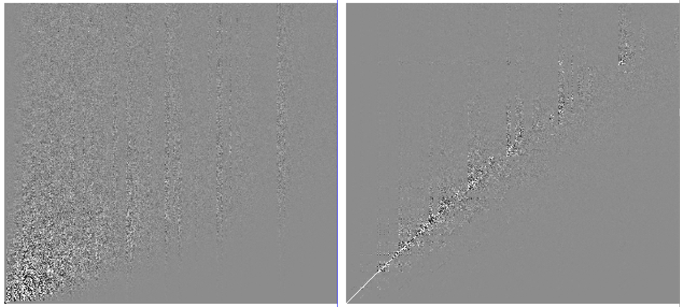
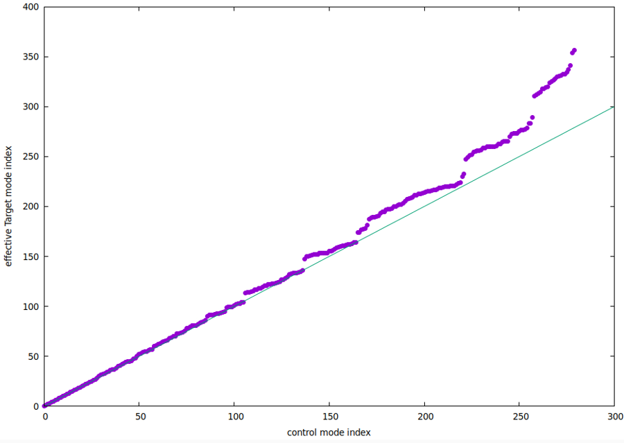
CMmWFSnin orthogonal target basis. The goal of the optimization is to rotate the control modes to make this decomposition as diagonal as possible - Perform rotations to drive the decomposition to a diagonal. Note that the input target modes may have some redundancy (null space), while the control modes do not. Consequently, the diagonal may be curved or slanted (skipping extra modes in null space), so this optimization iteratively tracks the “diagonal” and updates the optimization metric accordingly (values should cluster around the diagonal).
- Apply rotations to control modes in both WFS and DM space
Unless the target modes are constructed from the control modes, it is gererally not possible to reach a perfect match while enforcing WFS-space orthonormality. The optimization algorithm is iterative and drives the control modes to approach the target modes.
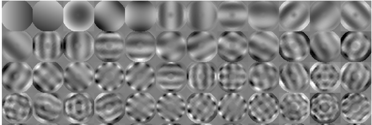
The figure below shows the resulting control modes in DM space.
To visualize how well the new control modes match the target modes, the files ./compfCM/matABr.fits shows how each control mode decomposes against the Gramm-Shmidt-processed target modes. The figure below shows this decomposition before (left) and after (right) the rotations are applied.
4.2. Handling DM edges
DM shape is controlled within the area defined by dmmask, and extrapolated beyond it. To avoid the unconstrained edges of the DM from exhibiting large excursions, extrapolation parameters can be tuned in the script.
The target modes are extrapolated when built. This is performed for Fourier modes by continuing the sine wave beyond the dmmask area, with a tapering down to zero. The mode is extended by a fixed number of pixel (actuator), plus a fraction of the mode spatial period. Use options -eo and -ef to change these settings.
If providing custom target DM modes, ensure they are properly extrapolated to avoid issues at the edges of dmmask.
5. Constructing CM by modal blocks
The CM may be contructed by blocks, where each block is set of modes over which a separate CM is computed. The multiple block-CMs are then merged into a single CM.
This approach is useful to implement modal control, where the first control modes are forced to be low-order wavefront modes (for example, having the first two modes be tip and tilt).
5.1. Constructing the modal basis
A modal basis is first created, or can be provided by the user. Modal blocks will be defined by picking modes from this basis. For example, to create a modal basis where the first 5 modes are Zerkines (tip, tilt, focus , astig (x2)), followed by Fourier modes of increasing spatial frequency:
# Create modal basis for RM acquisition
cacao-aorun-028-mkZFmodes -c0 0 -c1 16 -c 40 -ea 1.0 -t 1.0 -a 0.0
# File written to conf/RMmodesDM/modesZF.fits
With this basis, we will be able to select the first two modes as the first block to control tip-tilt, and define blocks according to spatial frequency.
The “ea” (edge apodization) parameter, together with the DM mask (file conf/dmmask.fits), define how modes are constructed to handle edge effect. Active DM actuators, defined by value=1 in dmmask, will be set to the analytical expression of the mode (here, a Zernike polynomial or a sine wave). For actuators outside the active area, the analytical form is convolved by a kernel of size proportional to the distance to the nearest ative actuators. The proportionality coefficient, set by parameter “-ea”, sets the degree to which the edge-softening is applied.

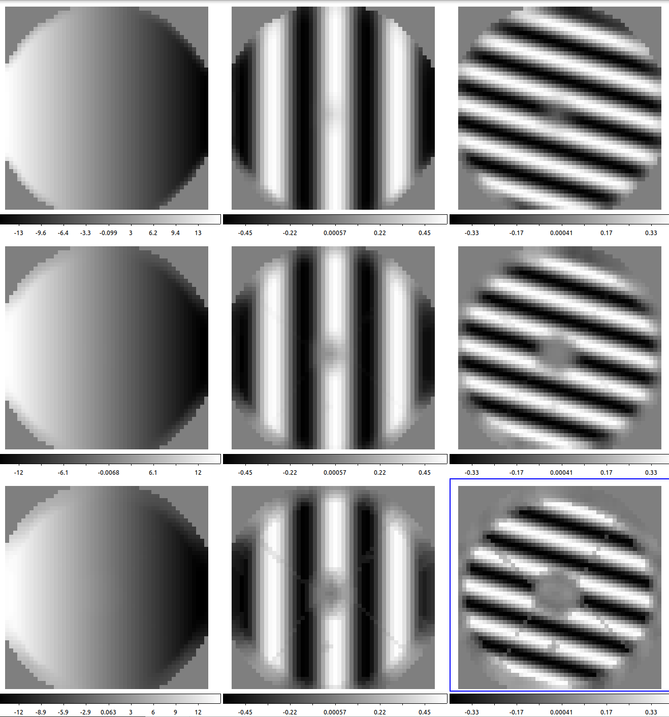
The edge apodization algorithm is designed to primarly attenuate high spatial frequencies while extrapolating low-order modes beyond the DM active area.
5.2. Modal response matrix
The modal response matrix cen be computed by multiplying the modal basis by the zonal response matrix, or it can be acquired.
To acquire it, poking the modes themselves on the DM:
# Acquire modal RM
cacao-fpsctrl setval measlinresp timing.NBave 5
cacao-fpsctrl setval measlinresp timing.NBexcl 5
cacao-aorun-030-acqlinResp -n 6 modesZF
5.3. Computing the block-CMs
We can now compute the CM for each block using the cacao-aorun-039-compstrCM script. The following options will be used:
- mode block tag (-mb option). This is the name of the block. We can use integers (“00”, “01”, “02” …) to keep track of the mode block ordering, or use more descrptive tags (“TT”, “LO”, “MO”, “HO”)
- mode block range (-mr option), specifying the set of modes to be selected for the block. For example, “1:5” will select the first 5 modes. Note the numbering starts at 1 (first mode = 1, not 0).
- set of blocks against which the current block should be marginalized (-marg option). While the SVD-based pseudoinverse ensures, whithin each block, that control modes are orthogonal in WFS space, it will not handle possible overlap between blocks. For example, if block “00” is tip-tilt, and we need to ensure that the current block does not contain tip-tilt, we add the “-marg 00” option to marginalize the current block against block “00”. Multiple blocks can be specified, separated by “:”.
Example:
# Compute CM
# Use GPU for all CMs
cacao-fpsctrl setval compstrCM GPUdevice 0
# Use SVD limit 0.1 for all CMs
cacao-fpsctrl setval compstrCM svdlim 0.1

# Compute CM for tip-tilt (first 2 modes of modesZF, so use range = 1:2)
# Write output to mode block 00
cacao-aorun-039-compstrCM -mb 00 -mr 1:2
# output files:
# ./conf/CMmodesWFS/CMmodesWFS.00.fits
# ./conf/CMmodesDM/CMmodesDM.00.fits

# block 01: LO modes, marginalized against TT
cacao-aorun-039-compstrCM -mb 01 -mr 3:10 -marg 00
# output files:
# ./conf/RMmodesWFS/RMmodesWFS.01.fits.m00
# ./conf/RMmodesDM/RMmodesDM.01.fits.m00
# ./conf/CMmodesWFS/CMmodesWFS.01.fits
# ./conf/CMmodesDM/CMmodesDM.01.fits
# Note the .m00 at the end of the RM filenames, indicating marginalization against block 00

# block 02: MO modes, marginalized against TT and LO
cacao-aorun-039-compstrCM -mb 02 -mr 11:50 -marg 00:01

# block 03: HO modes, marginalized against TT, LO, M)
cacao-aorun-039-compstrCM -mb 03 -mr 51:1249 -marg 00:01:02
Marginalization (-marg option) is performed in WFS space. To perform marginalization in DM space, use option -margDM. For example, to marginalize against the first two DM modes (usually tip-tilt) in DM space as well as previous blocks in WFS space, the command may be:
cacao-aorun-039-compstrCM -mb 01 -mr 3:10 -marg 00 -margDM
5.4. Merging block-CMs into a single CM
The cacao-aorun-039-compstrCM merge step will both combine block-CMs into a single file, and load it to shared memory.
When all block-CMs are computed, they are merged by running cacao-aorun-039-compstrCM with the “-mbm” option, specifying the set of blocks to be merged. For example, “-mbm 00:01:03:04” will merge blocks 00, 01, 03 and 04.
# Merge
cacao-aorun-039-compstrCM -mbm 00:01:02:03